19 Inch Rack Mount 42KW 48VDC Telecom Power Supply Telecom Rectifier 18KW Solar Module SNMP
1. Rack Mount Telecom Rectifier Overview
ET48700P300 is a 19-inch sub-rack for hybrid telecom power supply
system , with 15U height compact design to meet critical
application needs of fiber and microwave transmission, access
device, switch.
The system’s maximum power is 700A, with AC input/DC
input/battery/load MCBs. The cables are front accessing with MCB
and busbar. This power system supplies power to -48VDC
communication equipments.
2. Telecom Rectifier System Parameter
| Model | ET48700P300 |
| System | Dimension(mm) | 482.6(W)x350.6(D)x15U(H) |
| Weight | ≤ 50kg(without rectifier module) |
| Cooling mode | Forced air cooling |
| Installation mode | Installed on 19-inch rack or inside the cabinet |
| IP Grade | IP20 |
| AC Distribution | Input voltage | 380VAC, three phase |
| Input capacity | 1x125A/4P |
| Input frequency | 45~65Hz, rated 50/60Hz |
| AC SPD | 20kA/40kA, 8/20μs |
| PV Input capacity | 6x63A/2P |
DC Distribution | Output voltage | -42~-58VDC, rated value: -53.5VDC |
| Maximum capacity | 42kW(14x3000W rectifier module) |
| Battery breakers | 3x125A/3P |
| Load breakers | LLVD: 2x125A/1P, 2x63A/1P BLVD: 2x125A/1P, 2x63A/1P |
| DC SPD | 10kA/20kA, 8/20μs(designed inside) |
| PV Module | Input voltage | 120VDC to 425VDC, rated value: 340VDC |
| Efficiency | ≥96% |
| Output power | 3000W(200~425VDC) |
| Dimension | 106.5mm(W)×286mm(D)×41.5mm(1U/H) |
| Cooling mode | Forced cooling with fan |
| Rectifier Module | Input voltage | 85VAC-300VAC, rated value: 220VAC |
| Efficiency | ≥96% |
| Rated power | 3000W(176~300VAC ) |
| Dimension | 106.5mm(W)×286mm(D)×41.5mm(1U/H) |
| Cooling mode | Forced cooling with fan |
| Controller | Signal input | 3 AI(2 battery temp., 1 ambient temp) ,7 DI(SPD, 6 common DI) |
| Alarm output | 6 dry contact |
| Communication port | RS485/LAN Ethernet/SNMP |
| Display mode | LCD |
Environment | Operating temperature | -40℃~+65℃ |
| Storage temperature | -40℃~+70℃ |
| Operating humidity | 5%~95%(non-condensing) |
| Altitude | 0~3000m(If the altitude is within the range of 2000m to 3000m, the
maximum operating temperature decreases by 1℃ as the altitude
increases by 200m.) |
3. Telecom Rectifier Quick Details
Consists of distribution unit, rectifier module, photovoltaic
module, monitoring module. The configuration is optional, quick
details as below:
- Rectifier module: 3kwx14
- Photovoltaic module: 3kwx6
- Battery breakers: 3x125A/3P
- Load breakers: LLVD: 2x125A/1P, 2x63A/1P; BLVD: 2x125A/1P, 2x63A/1P
- Solar breakers: 6x63A/2P
- Controller: RS485/LAN Ethernet/SNMP
Pictures
Load/battery breakers:
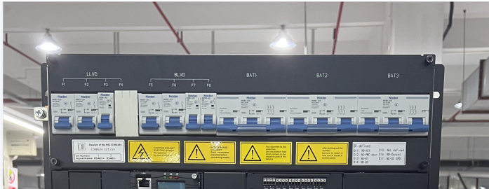
Photovoltaic module breakers:

Telecom rectifier system pictures:
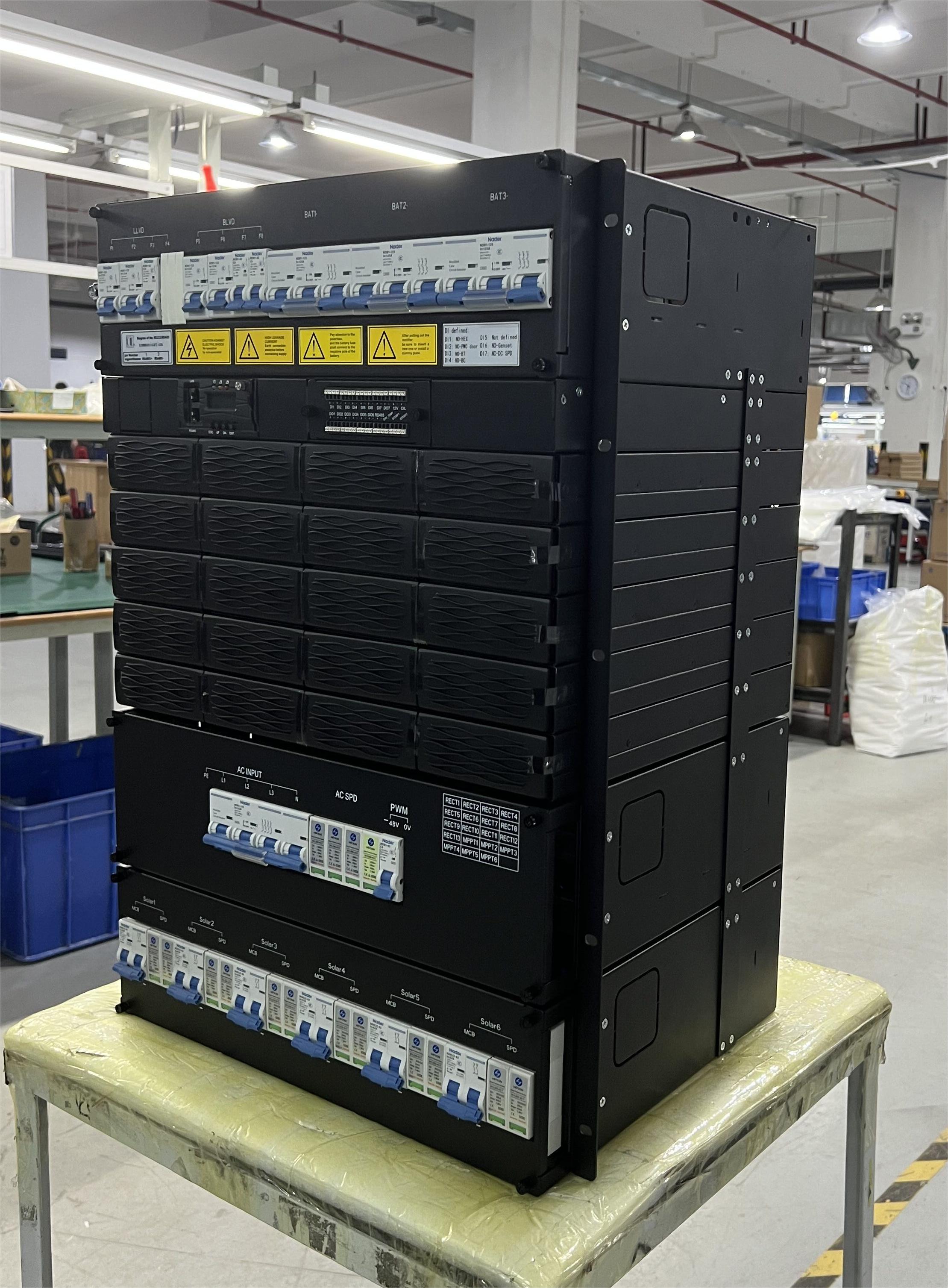
19 inch rack mounted telecom power supply pictures:

Telecom power supply production line:

4. Telecom Rectifier Working Principles
(1) Figure Conceptual Diagram shows the conceptual diagram. DC
power enters solar module through the DC power distribution unit
(PDU).
The solar module converts high-voltage into -48VDC. AC power enters
rectifiers through the AC PDU.The rectifiers convert the AC power
input into -48VDC power output, which is directed by the DC PDU to
DC loads along different routes.
(2) During normal operation, the solar module priority to the DC
load and charging batteries. When the solar power is low, the AC
power , rectifiers power DC loads and charge batteries. When both
the AC and solar are absent, rectifiers and solar modules stop
working and
batteries start to power loads. After the AC or solar power power
resumes, rectifiers or solar module power DC loads and charge
batteries again.
(3) The monitoring unit monitors the running state of each
component of the telecom power supply system in real time, and
carries out the corresponding intelligent control. When detecting a
fault, the monitoring module generates an alarm.
Figure Conceptual Diagram:

5. Telecom Rectifier Configuration Table
| Item | Configurations |
| Subrack | 3U AC input power distribution space 3U DC input power distribution space 3U DC output power distribution space 6U Module installation and monitor unit space |
| The power distribution unit | AC/DC input power distribution: AC input MCB, DC input MCB DC power distribution: battery low voltage disconnection (BLVD) route, load low voltage disconnection (LLVD) route, and battery route |
| Monitor unit | MC2600 |
| Rectifier module | A maximum of fourteen 3000W |
| Solar module | A maximum of six 3000W |
| AC SPD | Class C |
| DC SPD | PV Input:Class C |
| 48V Output:Class D |
6. Details of Rectifier Module And Solar Module
(6.1) The module panel
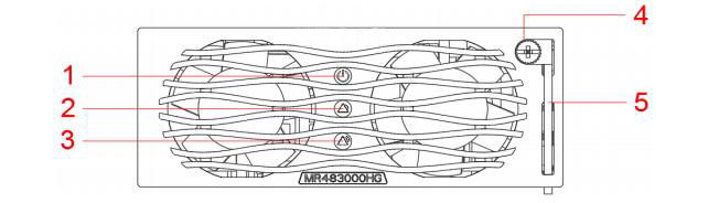
(1) Power indicator (2) Alarm indicator (3) Fault indicator
(4) Locking latch (5) Handle
There are three indicator on the panel,which are used to reflect
the operation status of the rectifier,see Table below for details.
| Indicator | Color | Status | Reasons for abnormal status |
| Power indicator | Green | Normally on | The module has and power input |
| Off | Main supply fault(no power input or OVP,UVP of power
input).non-output |
| Alarm indicator | Yellow | Normally on | Temperature alarm(OTP when the ambient temperature>65℃) |
| The module is hibernating. (indicator lighting, no alarm) |
| The module is current-limiting |
| Flickering | Communication failure |
Fault indicator | Red | Normally on | Non-output caused by module inner reason such as OVP, fan fault, OTP |
| Normally off | The module is running properly. |
(6.2) Solar Module Model MS483000HG Discription
Input Characteristics
| Input Voltage Range | 120VDC to 425VDC(power-up voltage is above 160VDC) |
| Rated Input Voltage | 340VDC |
| MPPT Voltage Range | 120VDC to 340VDC |
| Maximum Input Current | 17A |
| Surge Current | Standard: EN/IEC61000-4-5 |
| MPPT Precision | ≥99%@load≥400W |
| Reverse Polarity Protected | no damage even with the wrong polarity |
| Input Fuse | fuse both on the positive & negative polarities |
| Maximum Input Voltage | 450VAC(power good) |
Output Voltage | +54.5VDC |
Output Voltage Setting Value | +54.5±0.1VDC |
Adjustable Output Voltage Range | +42VDC~+58VDC |
Efficiency | ≥96%@340VDC/40%~70% Load- 54.5VDC |
Source Effect | ±0.1% |
Load Effect | ±0.5% |
(6.3) Rectifier Module Model MR483000HG2B-GS Discription
AC Input Characteristics
| Operating Voltage | 85VAC to 290VAC |
| Frequency | 45Hz-66Hz Rated value is 50Hz/60Hz |
Input Current | ≤ 18A |
| Power Factor | ≥0.99 ( 220VAC@20%-100% load ) |
| THD | ≤5% ( 50%-100% load ) |
Output Characteristics
| Output Voltage | 42V DC-58V DC Rated Value is 53.5 V DC |
| Linear Power Derating | 3000W (176V AC-290V AC) 3000W-1250W (175V AC-85V AC) |
| Regulated Voltage Precision | ≤±0.6% Vo |
Ripple and Noise | ≤200mVp-p(bandwidth≤20MHz) |
Standby power | ≤4W |
Startup duration | 3s~8s(Instant start mode) |
Output hold-up time | >10ms |
Phone noise weighting voltage | ≤2mV |
Wide-band noise voltage | 50mV(3.4kHz~150kHz)
≤20mV(0.15MHz~30MHz) |
(6.4) Communication between Rectifier/Solar Module & Monitoring
Module
CAN-bus communication mode is adopted between the rectifier/solar
module and the monitoring module. Remote software version upgrade
is supported, and the address of the module can be set through the
address board. When AC input disconnects, the module needs to
communicate with the host.
Isolation design is employed for CAN interface in the rectifier
module. The power supply of CAN is +5VDC, which is provided by the
rectifier/solar module internally.
The main monitoring information of the rectifier/solar module is as
below:
1) Voltage regulation and current regulation functions: meeting the
requirements of floating charging battery and voltage regulation;
2) Single module control of startup and shutdown;
3) Protection and Alarm Information Feedback:
- Mains fault: mains fault (AC input over-voltage/under-voltage);
- Module protection: temperature pre-alarm;
- Module fault: fan fault, over temperature shutdown or no output
caused by the module internally; (the module is in the state of
dormancy and shutdown, and the mains failure is not reported to the
module).
7. Controller-MC2600 (Monitoring Module)
The MC2600 front panel


(1) LAN port (2) RS485 port (3) Run indicator (4) Minor alarm
indicator
(5) Major alarm indicator (6) Handle (7) Buttons
Table for controller button description
| Button | Description |
| ESC | Returns to the previous menu without saving the settings. | Press the ESC and ENT button at the same time within a short period of time can restart the controller. |
ENT.
| Ø Enters the main menu from the standby screen. Ø Enters a submenu from the main menu. Ø Saves the menu settings. |
| UP | Turns to the previous menu or sets parameter values. When setting parameter values, you can hold down this button to
quickly adjust values. | When the parameter value is set by multiple string types, press up or down button to change each value. After setting the value, press the confirm button to move the cursor back automatically. |
| DN. | Turns to the next menu or sets parameter values.When setting
parameter values, you can hold down this button to quickly adjust
values. |
Describes the indicator on the controller panel is shown in table
below
| Type | Color | State | Instructions |
| Run indicator | Green | Flickering | Controller is running properly |
| Off | Controller is fault or has no DC input |
| Minor Alarm | Yellow | Normally on | The controller generates a minor alarm |
| Off | The controller does not generate any minor alarms |
| Major alarm | Red | Normally on | The controller generates a major alarm |
| Off | The controller does not generate any major alarms |
The controller provides two communication ports
The definition of RS485 communication port is shown in below table
| Pin No. | 1 | 2 | 3 | 4 | 5 | 6 | 7 | 8 |
| Signal name | RS485+ | - | RS485- | - | - | - | - | - |
The LAN Ethernet port interface definition is shown in Table
| Pin No. | 1 | 2 | 3 | 4 | 5 | 6 | 7 | 8 |
| Signal name | TX+ | TX- | RX+ | - | - | RX- | - | - |
8. DI/DO Interface
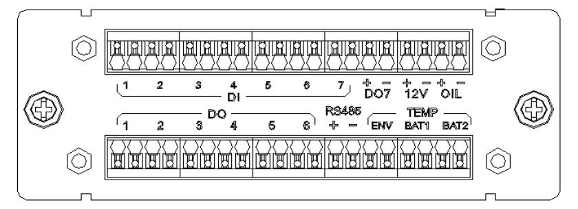
The DI/DO interface board front panel
Digital input is submenu of parameter setting menu, which is mainly
used for the operator to configure the input normal state of 8
digital switches in the system.
Table - Relay input parameter setting
| Digital No. | Digital name | DI Normal | Description |
| DI1 | HEX Alarm | NO | It is normal when opened; and the alarm occurs when closed. |
| DI2 | PWC Door Alarm | NC | It is normal when opened; and the alarm occurs when closed. |
| DI3 | BT Alarm | NO | It is normal when opened; and the alarm occurs when closed. |
| DI4 | BC Alarm | NO | It is normal when opened; and the alarm occurs when closed. |
| DI5 | Digital5 Alarm | NO | It is normal when opened; and the alarm occurs when closed. |
| DI6 | Genset on Alarm | NO | It is normal when opened; and the alarm occurs when closed. |
DI7 | DC SPD Alarm | NC | It is normal when opened; and the alarm occurs when closed. |
Relay output is submenu of parameter setting menu, which is mainly
used for the operator to configure the output normal state of 8
relays in the system.
Table - Relay output parameter setting
| Digital No. | Digital Name | Alarm code | Description |
| DO1 | Relay output 1 | NC | Closed when normal,opened when associated alarm occurs. |
| DO2 | Relay output 2 | NC | Closed when normal,opened when associated alarm occurs. |
| DO3 | Relay output 3 | NC | Closed when normal,opened when associated alarm occurs. |
| DO4 | Relay output 4 | NC | Closed when normal,opened when associated alarm occurs. |
| DO5 | Relay output 5 | NC | Closed when normal,opened when associated alarm occurs. |
| DO6 | Relay output 6 | NC | Closed when normal,opened when associated alarm occurs. |
In addition, the product provides 6 other ports.
Table - Other intput parameter setting
| Parameter name | Setting description |
| BTEMP 1 | Battery sensor1 port |
| BTEMP 2 | Battery sensor2 port |
| ENV_TEMP | Enveropment sensor port |
| 12V +/- | 12V power supply is provided |
| RS485 | RS485 port, reserved interface, no protocol definition |
| OIL+/- | Connect the oil level sensor |
9. Install Subrack
Install the subrack to the 19-inch rack, as shown in Figure below.
Ø Step 1,Remove the plug from the package.
Ø Step 2,Push the plug into the 19-inch rack
Ø Step 3,Install the fixed screw (if the mounting hole of the plug
frame ear does not correspond to the position of the floating nut
of the frame,
it needs to be adjusted according to the actual installation).

Install Rectifier/Solar module
Ø Step 1, Take out the module from the package.
Ø Step 2, Hold the module handle on the front panel and put the
module onto the slot.
Ø Step 3, Push the module slowly to the front panel of the module
and flush with the power
distribution panel.
Ø Step 4, Tighten the fixing screw on the module panel so that the
module does not come off.

10. Packing and Shipping
Package use free fumigation woodcase which is suitable for export.
This package is anti moisture, anti impact and srong to ensure safe
transportation.


